SECTION 5 - ENGINE INSTALLATION AND MARKING OFF
1 2  3  |
Step 1 - Mark and remove side panels of engine bayNow once again this depends on how you have designed your subframe. Now mine has rails that basically sit exactly where the sides of the engine bay are so therefore I have to remove the lower part of the skirt on the left and right hand side of the engine bay (See photo 1) so that the frame can rise up to meet the bolting points at the front and the back. You may have to do quite a bit of hacking to this side to allow room for the frame. Some people end up hacking the whole side away. I am going to try and avoid this if possible. One other thing you may have to consider is the making of a small recess for the actual engine mount on the left hand side (See photo 2). With the frame in and having a good idea where the engine mount sits I might get away with not having to make much of an impression here which would be nice. Regarding the right hand side of the engine bay, basically this is a mirror image of the left as I made the frame geometric, so the spar is mimicked on this side. Basically with both sides you are drawing a horizontal line from the top of the cone tower to the front of the engine bay (as per images 1 & 2). You may have to go past the seam weld at the front of the engine bay depending on the design of your frame. Also as you can see in Image 1 there isn't a lot of panel left as this is where the old thermo fan sat. I will be welding a plate there to re-inclose this side of the engine bay. Tools to use. Well I just used my trusty jigsaw with a steel cutting blade. This thing is supposedly good for up to 3mm, which is a lot heavier than 1/16 gauge (or less) automotive panel. So no problems there I suspect. |
||||
| 1  2  3  4  5  6  7  8  9  |
Step 2 - Place subframe into the car.This where you get to find out if the whole thing fits...Well actually not really because if you read the previous section I told you about not finalising the design of the subframe until you have dropped it in the engine bay a couple of times to confirm mounting points. Install the subframe back into the car. Hopefully if you have welded things correctly it should fit. If it doesn't you need to start measuring and isolating where it doesn't fit and why. Then it is a case of removing the subframe and rectifying the situation. If it is not meeting at the cone towers this could be a big problem. Case History: If you are a member of Ausmini forum, you will have seen that my subframe didn't meet up with the subframe stud holes. This was most likely because with all the moving around of the subframe by the time I went to weld in the back cross brace the cones had move together by a ¼�. I then removed the brace and the frame could flex outward and she went in easily. It may be an idea to fully bolt up the subframe before putting in some of these reinforcing struts. I placed the down spars with the frame in situ and they met up with the bolting holes perfectly. Something to keep in mind. Any other problem should be less work, as it may be a case of just shortening a spar. Good Luck. But hopefully if you have taken a systematic approach to it the tolerances should be pretty small. The main thing you want to be sure of is that the engine is level left to right and parallel to the rear of the subframe. Update 30/10/04: As you can see it fits. I have to take the studs out of the other subframe to bolt her up and the cutting of the engine walls isn't quite complete but she seem to fit pretty well. I also have to remove all the paraphernalia from the hydrolastic suspension but it all seems good otherwise. I will bolt her into place and then start making measurements and welding the front section on then that should be the subframe and then comes the engine mounts! Update 5 November 2004: Well the subframe is in and now I can start measuring the down spars. This will require a bit more work with the angle grinder as I have decided that if I want to take the subframe in and out at any later stage then I should take account of this now. So basically I will cut a line straight down at 90 degrees to the cross cut. This will also allow for unimpeded access for the down spar on the left hand side, and will allow the frame to drop out the bottom with less trouble. Photos to follow. Update 6/11/04: Well have tack welded all the front bits (images 4, 5 & 6). As you can see one of the front mounting plates wasn't tacky enough and under bolting pressure the tacks gave way oh well. Still getting close to the point of dropping the engine in to do measurements for the engine mounts still only going to do that after I have mounted all the suspension and she is sitting on the ground otherwise things could go out of wack. Well as at the end of Sunday (see images 6, 7 & 8) I have pretty much finished the subframe! I have to re-weld the mounting plate on the right hand front of the subframe but apart form this she is pretty much finished. Unfortunately I bolted her in before taking a final picture, but apart from some added plates there wasn't much difference.
|
||||
1 2 2 3 3 4  |
Step 3 - Detail/Overhaul engine prior to placement in the carThis is something you will probably want to put off depending on the state of your halfcut. But don't be lazy as you will have to do it sooner or later. And it is important. Now there is two aspects to this section. The first being the detailing of the engine (in other words making it look pretty (bling bling as Mick pointed out)). The second being basic maintenance as outlined in the warranty document provided by Rolin Automotive. DetailingI have only my engine to go off so here goes. All the aluminium bits on the engine were a little worse for wear due to the being out in the elements. So the aluminium had oxidised and there was minor surface rust on the block (obviously the engine in not all alloy). But overall none was serious. I ended up using a substance called "Blitz" which a non Hydrochloric based aluminium cleaner. Uses Phosphoric acid. Anyway did a reasonable job. Stains still a little evident but really got rid of the oxide and as I am painting it this is not a big concern it is the oxide that will lift the paint. Now with everything still attached is can be very difficult to access alot of the engine. For this reason I have removed the valve cover and it made bringing this up to scratch a lot easier (see Image 2). I will also remove the gearbox from the engine so that I can make a decent job of spraying the gearbox. As for the block I intend to scrub it back and repair the paint currently on the engine but not much more. I also going to leave the intake plenum which was quite oxidised. I have scrubbed it but that is it. Engine OverhaulNow the most critical element is the timing belt. My engine has 97,000Kms on the clock and the belt should be replaced every 100,000Kms so it is due. The warranty actually states that you MUST change the belt irrespective of the mileage of the engine. See section 2 step 5 for a full run down of warranty conditions. As stated previously warranties are pretty much useless in my opinion, and the fact that I am putting it in a Mini probably voids the warranty anyway. I was thinking about replacing the sump gasket aswell and painting the sump red to match the valve cover but I need to source a sump gasket (This is the same problem I face with the cam belt). UpdatesNo updates as at 1 September, 2005 |
||||
1 2  3  4  5  |
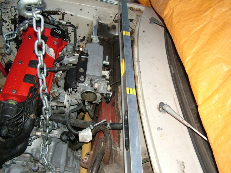
Step 4 - Place engine into subframeNote: Have decided that I must have the car on the ground with the suspension fully functioning and the wheels on before inserting the engine, as deciding where everything goes with the car not sitting as per usual may lead to a bad fitment. Plus it would be nice to see how the suspension looks and tests before installing the engine. This could be a bit tricky depending on your design for the subframe. But unlike the actual starlet (where removal from above was impossible), you should be able to put it in from the top. So drop it in and line up the engine mounts. Having got it in the engine bay as you can see, I can honestly say that this is easier said than done. But I got it in there. As you can see in picture 4 the engine is not sitting perfectly horizontal. This is ok as I know why. I rushed things a bit and left a few things in place that I shouldn't have. So before installing the engine to check things make sure you're not lazy like me and remove all remnants of the old car from the engine bay with the exception of the master cylinders as these are necessary to ensure you don't move the engine too far back. There is more information in the next step on how locate the engine for the creation of the engine mounts. But at least this is proof that the engine will fit inside the engine bay and also that my design wasn't completely flawed as things are meeting up as will be demonstrated in the next point when I start designing the engine mounts and show you how to ensure that the engine is sitting properly before you start.
|
||||
11 12  13  14  |
Step 5 - Marking Up and Engine PlacementMotor Installation for marking off: Lower the engine into the engine bay. Orientate the engine into the specific location. Now where's this? Well that is pretty difficult to explain (I will supply pictures where I can). But here are a few ideas about cues to use to make sure the engine is orientated correctly:
This is a black art but if you have decent eye you should be able to spot whether the engine is out of alignment. But don't slack off on this as it is probably the most important aspect of the actual engine installation. Another thing is the amount of space at the front for such things as the relocated alternator, oil filter and also space for a radiator and possibly the relocated FMIC (front mounted intercooler). Regarding the intercooler this will present an interesting challenge, as I am determined for it to be located by some form of front mounting. The only trouble is I think I may have to get a custom intercooler made which is big, big bucks (between $500 and $1500). Note: Brad pointed out a helpful hint to me the other day concerning putting all the jazzy gear on the engine prior to getting it certified and registered. The Hint, don't do it. In other words do a stock installation for rego and then once registered do all your changes. Technically this is perfectly legal as the car will be registered as a turbo vehicle. Once you are satisfied that you have the engine in the right spot, try to secure it in this location so that it won't move while you're working around it. My engine is currently sitting on blocks to maintain the correct level from the ground and chocks around the frame to keep it correct upright location. Create mockups of the engine mount flanges and use these to create the real ones. Or end up welding and grinding off plates as you try to get the right. Another solution is to create the frame based mounts themselves and bolt them to the engine and then lower the engine back to the frame making slight adjustments as you go. This is probably the best approach and ensures you get it right the first time. I ended removing the remnants of the current mount and using this approach. |
||||
FINAL NOTE: While I have endevoured to give you as much information as I can, I am not a professional engineer, not even close. So anything you take from this website is at your own risk. Due to the increasingly litigous society in which we dwell I am will also be unable to develop or send out full specs for the subframe. For the same reason I won't be making subframes for people. The fact is as much as people like to say that they won't seek you out when things go wrong they will and usually with a lawyer in tow. |
|||||


ON TO SECTION 6 - CREATING THE ENGINE MOUNTS
BACK TO STEP 4 - CREATING THE SUBFRAME
BACK TO START - STARLET GT CONVERSION